Electromagnetic or electronic ballast for fluorescent lamps necessary for the normal operation of this light source. The main task of the ballast is to convert direct voltage into alternating voltage. Each of them has its pros and cons.
How does LL work with electromagnetic ballast?
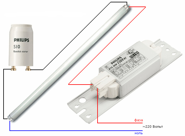
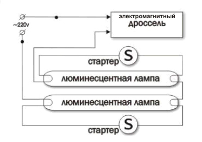
 Scheme of connecting the ballast to the LL
 Pay attention to this wiring diagram. Marking LL1 is a ballast. Inside the fluorescent lamps is a gaseous medium. With increasing current, the voltage between the electrodes in the lamp gradually decreases, and the resistance is negative. The ballast is used just to limit the current, and also creates an increased short-term lamp ignition voltage, since it is not enough in a conventional network. This element is also called a throttle.
In such a device, a starter is used - a small glow discharge lamp (E1). It contains two electrodes. One of them is bimetallic (movable).
In their original position, they are open. By closing contact SA1 and applying voltage to the circuit, the current does not first pass through the light source, but a glow discharge appears in the starter between the two electrodes. The electrodes are heated, and the bimetallic plate bends as a result, closing the contact. The current passing through the ballast increases, heating the electrodes of the fluorescent lamp.
Next, the electrodes in the starter open. There is a process of self-induction. The inductor creates a high voltage pulse, which ignites the LL. The rated current passes through it, but then it drops by half due to a decrease in the voltage across the inductor. The starter electrodes remain in the open position as long as the light is on. And capacitors C2 and C1 increase efficiency and reduce reactive loads.
 Connecting fluorescent lamps
 Advantages of classic electromagnetic ballast:
- low cost;
- ease of use.
Cons of EMPR:
- noise of the working throttle;
- flicker LL;
- long ignition of the lamp;
- weight and large dimensions;
- up to 15% of energy losses due to phase advance of the alternating voltage (power factor);
- poor switching in low temperature environment.
On a note! The problem of energy loss can be solved by connecting (in parallel to the network) a capacitor with a capacitance of 3-5 microfarads.
Advice! The ballast must be selected strictly in accordance with the power of the lamp. Otherwise, your lamp may break prematurely.
The most common causes of LL malfunctions with electromagnetic ballast
The following problems are identified:

How LL works with electronic ballast
Due to the mass of shortcomings of the electromagnetic ballast, a new, more durable and technological electronic ballast was created. This is a single electronic power supply. Now it is the most common, as it is devoid of the shortcomings that exist in the EMPRA. In addition, it works without starters.
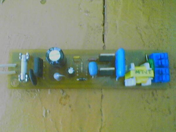
For example, let's take a diagram of any electronic ballast.
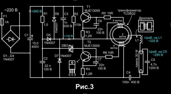
The input voltage is rectified, as usual, by diodes VD4-VD7. Then comes the filter capacitor C1. Its capacity depends on the power of the lamp. Usually guided by the calculation: 1 uF per 1 W of consumer power.
Next, the capacitor C4 is charged and the dinistor CD1 breaks through. The resulting voltage pulse activates the transistor T2, after which a half-bridge self-oscillator is connected to the work from the transformer TR1 and transistors T1 and T2.
The electrodes of the lamp begin to warm up. To this is added an oscillatory circuit, which enters into electrical resonance before discharging from the inductor L1, the generator and capacitors C2 and C3. Its frequency is about 50 kHz. As soon as the capacitor C3 is charged to the trigger voltage, the cathodes are intensely heated, and the LL is ignited smoothly. The inductor immediately limits the current, and the generator frequency drops. The oscillatory circuit goes out of resonance, and the rated operating voltage is established.
Advantages of electronic ballasts:
- low weight and small dimensions due to high frequency;
- high light output due to increased efficiency;
- LL has no blinking;
- protection of the lamp from voltage drops;
- no noise during operation;
- durability due to optimization of the start-up and operation mode;
- It is possible to set instant start or delayed start.
The disadvantage of electronic ballasts is only the high cost.
Note! An electronic cheap ballast for fluorescent lamps works like an EMPRA: a fluorescent lamp is ignited from a high voltage, and the combustion is kept low.
The cause of breakdowns of lamps with electronic ballast, as well as their repair
Yes, nothing is permanent. They break too. But the repair of electronic ballast is much more difficult than that of electromagnetic. Here you need skills in soldering and knowledge of radio engineering. And it doesn’t hurt to also know how to check the electronic ballast for operability if there is no known working LL.
Remove the lamp from the fixture. Close the leads of the filaments, for example, with a paper clip. And between them connect an incandescent lamp. See the picture below.
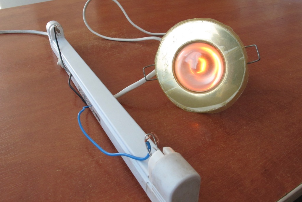
When power is applied, a working ballast will light the bulb.
Advice! After repairing the ballast, before connecting it to the network, it is better to connect one more incandescent lamp (40 W) in series. This is to the fact that if a short circuit is detected, it will light up brightly, and the parts of the device will remain unharmed.
Most often, 5 parts “fly out” in the electronic ballast:
- Fuse (2-5 ohm resistor).
- Diode bridge.
- Transistors. Together with them, 30 ohm resistors can also burn down the circuit. They fail mainly due to power surges.
- A little less often, a breakdown of the capacitor connecting the filaments is detected. Its capacitance is only 4.7 nF. In cheap lamps, they put such film capacitors with an operating voltage of 250 - 400 V. This is very small, so it is better to replace them with capacitors of the same capacity, only with a voltage of 1.2 kV, or even 2 kV.
- Dinistor. Often referred to as DB3 or CD1. It is impossible to check it without special equipment. Therefore, if all the elements on the board are intact, and the ballast still does not work, try installing another dinistor.
If you do not have knowledge and experience in electronics, it is better to simply replace your ballast with a new one. Now each of them is produced with instructions and a diagram on the case. Having carefully read it, you can easily connect the ballast yourself.
Fluorescent lamps do not work directly from a 220 volt network. They need a special adapter that will stabilize the voltage and smooth out the current ripple. This device is called ballast (ballast), consisting of a choke, with which the ripple is smoothed, a starter used as a starter, and a capacitor to stabilize the voltage. True, the PRA in this form is an old block, which is gradually being phased out. The thing is that it was replaced by a new model - an electronic ballast, that is, the same ballast, only of an electronic type. So, let's look at the electronic ballast - what it is, its circuit and main components.
The design and principle of operation of electronic ballasts
In fact, an electronic ballast is an electronic plateau, of a small size, which includes several special electronic element. The compact design makes it possible to install a plateau in the luminaire instead of a choke, starter and capacitor, which together take up more space than electronic ballasts. At the same time, the connection scheme is quite simple. More about her below.
Advantages
- The fluorescent lamp with electronic ballast turns on quickly, but smoothly.
- She doesn't blink or make noise.
- Power factor - 0.95.
- The new block practically does not heat up compared to the outdated one, and this is a direct saving of electric current up to 22%.
- The new starting block is equipped with several types of lamp protection, which increases its fire safety, operational safety, and also extends the service life several times.
- Providing a smooth glow, without flicker.
Attention! Modern labor protection rules prescribe the use of fluorescent lamps equipped with precisely this new equipment in workrooms.
Device diagram
Let's start with the fact that fluorescent lamps are gas-discharge light sources that work according to the following technology. The glass flask contains mercury vapor, into which an electric discharge is applied. This is what produces ultraviolet light. A layer of phosphor is applied to the flask itself from the inside, which converts ultraviolet rays into visible to the eye light. There is always negative resistance inside the lamp, which is why they cannot work from a 220 volt network.
But here it is necessary to fulfill two main conditions:
- Heat up two filaments.
- Create a large voltage up to 600 volts.
Attention! The magnitude of the voltage is directly proportional to the length of the fluorescent lamp. That is, for short lamps with a power of 18 W it is less, for long lamps with a power above 36 W it is more.
Now the electronic ballast circuit itself.
Let's start with the fact that fluorescent lamps, for example, LVO 4 × 18, with the old block always flickered and made an unpleasant noise. To avoid this, it is necessary to apply a current to it with an oscillation frequency of more than 20 kHz. To do this, you will have to increase the power factor of the light source. Therefore, the reactive current must be returned to a special storage of an intermediate type, and not to the network. By the way, the drive is not connected to the network in any way, but it is it that feeds the lamp if a network voltage transition occurs through zero.
How does it work
So, the mains voltage of 220 volts (it is variable) is converted into a constant with an indicator of 260-270 volts. Smoothing is performed using an electrolytic capacitor C1.
After that, the DC voltage must be converted into a high-frequency voltage up to 38 kHz. A half-bridge push-pull type converter is responsible for this. The composition of the latter includes two active elements, which are two high-voltage transistors (bipolar). They are usually called keys. It is the possibility of converting direct voltage into high-frequency voltage that makes it possible to reduce the dimensions of electronic ballasts.
A transformer is also present in the device (ballast) circuit. It is both the control element of the converter and the load for it. This transformer has three windings:
- One of them is working, in which there are only two turns. Through it there is a load on the chain.
- Two are managers. Each has four turns.
A symmetrical type dinistor plays a special role in this entire electrical circuit. In the diagram, it is designated as DB3. So this element is responsible for starting the converter. As soon as the voltage in the connections of its connection exceeds the allowable threshold, it opens and sends a pulse to the transistor. After that, the converter as a whole starts up.
- From the control windings of the transformer, the pulses are fed to the transistor switches. These pulses are out of phase. By the way, opening the keys causes pickup on two windings and on the working one too.
- An alternating voltage from the working winding is supplied to the fluorescent lamp through elements installed in series: the first and second filament.
Attention! The capacitance and inductance in the electrical circuit are selected in such a way that voltage resonance occurs in it. But at the same time, the frequency of the converter must be unchanged.
Note that capacitor C5 will experience the largest voltage drop. It is this element that lights the fluorescent lamp. That is, it turns out that the maximum current heats up two filaments, and the voltage across the capacitor C5 (it is large) ignites the light source.
Essentially, a glowing lamp should lower its resistance. This is true, but the reduction is negligible, so the resonant voltage is still present in the circuit. This is the reason why the lamp continues to glow. Although the L1 inductor creates current limits on the resistance difference indicator.
The inverter continues to operate in automatic mode after startup. At the same time, its frequency does not change, that is, it is identical to the start frequency. By the way, the launch itself lasts less than one second.
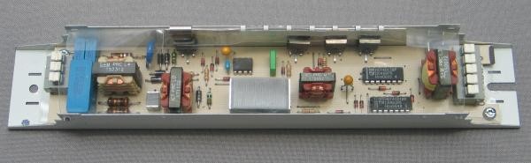
Testing
Before putting the electronic ballast into production, all kinds of tests were carried out, which indicate that the built-in fluorescent lamp can operate in a fairly wide range of voltages applied to it. The range was 100-220 volts. It turned out that the frequency of the converter changes in the following sequence:
- At 220 volts, it was 38 kHz.
- At 100 volts 56 kHz.
But it should be noted that when the voltage is reduced to 100 volts, the brightness of the light source has clearly decreased. And one moment. A fluorescent lamp is always supplied with AC current. This creates conditions for its uniform wear. Or rather, the wear of its filaments. That is, the life of the lamp itself increases. When testing the lamp with direct current, its service life was halved.
Causes of malfunctions
So, for what reasons can a fluorescent lamp not burn?
- Cracks in the places of soldering on the board. The thing is that when the lamp is turned on, the board starts to heat up. After it is turned on, the electronic ballast cools down. Temperature fluctuations negatively affect the soldering points, so there is a possibility of circuit breakage. You can fix the problem by soldering the breakage or even by simply cleaning it.
- If there is a break in the filament, then the electronic ballast itself remains in good condition. So this problem can be solved simply - replace the burned-out lamp with a new one.
- Power surges are the main cause of failure of electronic gear components. Most often, the transistor fails. Manufacturers of ballasts did not complicate the circuit, so there are no varistors in it, which would be responsible for the jumps. By the way, the fuse installed in the circuit also does not save from power surges. It works only if one of the elements of the circuit is broken. Therefore, advice - power surges are usually present in bad weather, so you should not turn on the fluorescent lamp when there is heavy rain or wind outside the window.
- The connection diagram of the device to the lamps was incorrectly drawn.
It is interesting
Currently, electronic ballasts are installed not only with gas-discharge light sources, but also with halogen and LED lamps. In this case, you cannot use one device designed for one type of lamp to another lamp. First, they don't fit. Secondly, they have different schemes.
When choosing an electronic ballast, it is necessary to take into account the power of the lamp in which it will be installed.
The best version of the model is devices with protection against non-standard modes of operation of the light source and from their deactivation.
Be sure to pay attention to the position in the passport or instructions, which indicates in what weather and climatic conditions the electronic ballast can operate. This affects both the quality of operation and the service life.
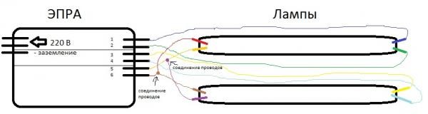
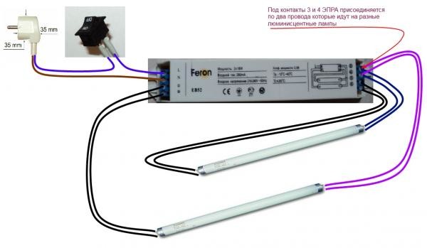
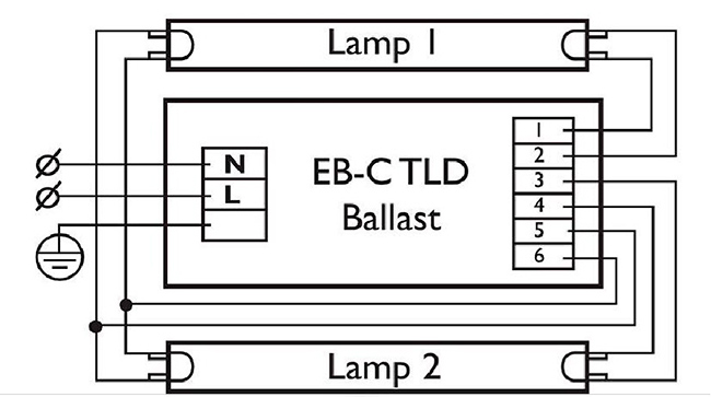
And the last is the wiring diagram. In principle, nothing complicated. Usually, the manufacturer directly on the box indicates this same connection diagram, where both the numbers and the connection circuit are indicated exactly by the terminals. Usually for the input circuit there are three terminals: zero, phase and ground. For the output to the lamps - two terminals, that is, in pairs, for each lamp.
Related posts:
Fluorescent lamps are already quite firmly and have long entered the lives of most people. Now they are becoming more and more popular, because electricity is constantly becoming more expensive and using conventional incandescent lamps is too expensive. It is also known that not everyone can buy compact energy-saving lamps, in addition, most modern chandeliers need a large number of such lamps, which raises doubts about their efficiency. That is why in many modern apartments fluorescent fluorescent lights are installed, which is helped by a fluorescent lamp circuit, on which you can see the principles of its operation.
The device of fluorescent lamps
To understand the principles of operation of a fluorescent lamp, it is necessary to study its structure. It consists of a thin cylindrical flask made of glass, which has different shapes and diameters. Fluorescent lamps are of several types:
- U-shaped;
- straight;
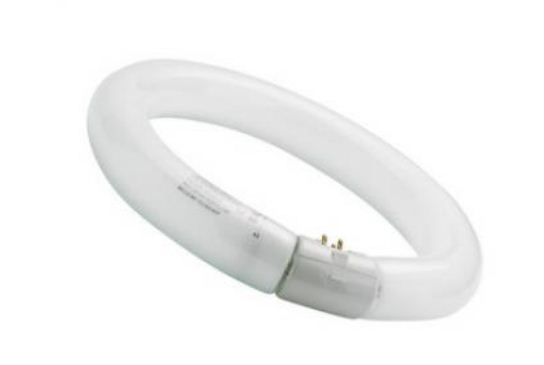
- ring;
- compact (with special sockets E14, as well as E27).
All of them have a different appearance, but they are united by the presence of electrodes, a luminescent coating and an injected inert gas with mercury vapor inside. The electrodes are small spirals that heat up for a short period of time, thus igniting the gas, due to which the phosphor that is applied to the walls of the lamp glows. It is known that ignition coils are small in size, so the standard voltage that is in the home electrical network is not suitable for them. Therefore, for these purposes, they use specialized devices called chokes, with their help, the current strength is limited to the desired value, thanks to their inductive resistance. In addition, so that the spiral can quickly warm up, but not burn out, the fluorescent lamp circuit also shows a starter that turns off the glow of the electrodes after the gas in the lamp tubes ignites.
Principles of operation of fluorescent lamps
During operation, a voltage of 220V is applied to the terminals, passing through the choke directly to the first spiral of this lamp. Then it goes to the starter, which works, and also passes current to the spiral, which is connected to the mains terminal. This is demonstrated by the connection diagram for fluorescent lamps.
Quite often, a capacitor can be installed on the input terminals, which plays the role of a specialized mains filter. It is thanks to his work that a particle of the reactive power generated during the operation of the throttle is extinguished. The result is that the lamp consumes less electricity.
Checking fluorescent lamps
 If your lamp has stopped igniting, the likely cause of this malfunction is a break in the tungsten filament that heats the gas and causes the phosphor to glow. During operation, tungsten evaporates over time, starting to settle on the walls of the lamp. In the process, the glass bulb at the edges has a dark coating, which warns of a possible failure of this device.
It is very simple to check the integrity of the tungsten filament, you need to take an ordinary tester that measures the resistance of the conductor, after which you need to touch the probes to the output ends of this lamp. If the device shows, for example, a resistance of 9.9 ohms, then this will mean that the thread is intact. If, during the test of a pair of electrodes, the tester shows a full zero, this side has a break, so the fluorescent lamps will not turn on.
The spiral can break due to the fact that during the time of its use the thread becomes thinner, so the tension that passes through it gradually increases. Due to the fact that the voltage is constantly increasing, the starter fails, which can be seen from the characteristic “blinking” of these lamps. After the burned-out lamps and starters are replaced, the circuit will work without adjustments.
If, when the lamps are turned on, you hear extraneous sounds or you will feel the smell of burning, then it is necessary to immediately de-energize the lamp, checking the performance of its elements. It may be that slack has appeared on the terminal connections themselves and the wire connection is warming up. In addition, in the case of poor-quality manufacture of the inductor, a turn-to-turn circuit of the windings may occur, which will lead to the failure of the lamps.
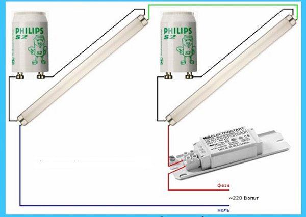
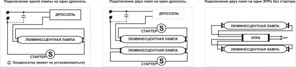
How to connect a fluorescent lamp?
Connecting a fluorescent lamp is a very simple process, its circuit is designed to ignite only one lamp. To connect a pair of fluorescent lamps, you need to slightly change the circuit, while acting on the same principle of connecting elements in series.
In such a case, it is necessary to use a pair of starters, one per lamp. When connecting a pair of lamps to a single choke, it is imperative to take into account its rated power indicated on the case. For example, if its power is 40 W, then it is possible to connect a pair of identical lamps to it, the maximum load of which is 20 W.
In addition, there is a fluorescent lamp connection that does not use starters. Thanks to the use of specialized electronic ballast devices, the lamp starts up instantly, without "blinking" the starter control circuits.
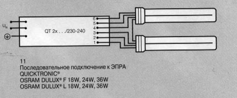
Connecting a fluorescent lamp to an electronic ballast
 Connecting the lamp to electronic ballasts is very simple, because their case contains detailed information, as well as a schematic showing the connection of the lamp contacts with the corresponding terminals. However, to make it more clear how to connect a fluorescent lamp to this device, you can simply carefully study the diagram.
The main advantage of this connection is the absence of additional elements that are needed for starter circuits that control lamps. In addition, with the simplification of the circuit, the reliability of the operation of the entire lamp increases significantly, because additional connections with starters, which are rather unreliable devices, are excluded.
Basically, all the wires that are needed to assemble the circuit come with the electronic ballast itself, so there is no need to reinvent the wheel, invent something and incur additional costs for the purchase of missing elements. In this video clip you can learn more about the principles of operation and connection of fluorescent lamps:
Post navigation
The distinctive principle of the wiring diagram fluorescent lamps consists in the need to include in it devices of a starting type, the duration of operation depends on them.
In order to understand the circuits, it is necessary to understand the principle of operation of these fixtures.
A luminescent type lamp device is a sealed vessel filled with a special gas mixture. The calculation of the mixture was carried out in order to waste less gas ionization energy in comparison with conventional lamps, due to this, you can save a lot on lighting a house or apartment.
For constant illumination, it is necessary to hold the glow discharge. This process is ensured by supplying the desired voltage. The problem lies only in the following situation - such a discharge appears from the supply voltage, which is higher than the working one. But this problem was also solved by the manufacturers.
On both sides of the lamp, electrodes are installed that receive voltage and maintain the discharge. Each electrode has two contacts with which the current source is connected. Due to this, the zone that surrounds the electrodes is heated.
The lamp lights up after heating each electrode. This happens due to the impact on them of high-voltage pulses and the subsequent work of the voltage.
When exposed to a discharge, the gases in the lamp container activate the emission of ultraviolet light, which is not perceived by the human eye. In order for human vision to distinguish this glow, the bulb inside is covered with a phosphor substance, which shifts the frequency interval of illumination to the visible interval.
By changing the structure of this substance, a change in the range of color temperatures occurs.
Important! You can not simply turn on the lamp in the network. The arc will appear after the heating of the electrodes and the pulsed voltage are ensured.
Special ballasts help to provide such conditions.
The nuances of the connection scheme
A circuit of this type must include the presence of a throttle and a starter.
The starter looks like a small source of neon lighting. To power it, you need an AC power supply, and it is also equipped with a certain number of bimetallic contacts.
The choke, starter contacts and electrode threads are connected in series.
Another option is possible when replacing the starter with a button from the input call.
The voltage will be carried out by holding the button in the pressed state. When the lamp is lit, it must be released.
- the connected choke stores electromagnetic energy;
- with the help of starter contacts, electricity is supplied;
- current transfer is carried out with the help of tungsten filaments heating electrodes;
- heating of electrodes and starter;
- then the starter contacts open;
- the energy that is accumulated with the help of the throttle is released;
- the lamp turns on.
In order to increase the score useful action, to reduce interference, two capacitors are introduced into the circuit model.
The advantages of this scheme:
Simplicity;
Democratic price;
She is reliable;
The disadvantages of the scheme:
Large mass of the device;
Noisy work;
The lamp flickers, which is not good for vision;
Consumes a large amount of electricity;
The device turns on for about three seconds;
Poor performance at sub-zero temperatures.
Connection sequence
Connection using the above scheme occurs with starters. The option considered below has a 4-65W starter model S10, a 40W lamp and the same power at the throttle.
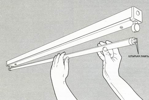
Stage 1. Connecting the starter to the pin contacts of the lamp, which look like incandescent filaments.
Stage 2. The remaining contacts are connected to the throttle.
Stage 3. The capacitor is connected to the power contacts in parallel. Due to the capacitor, the reactive power level is compensated, and the amount of interference is reduced.
Features of the connection diagram
Due to the electronic ballast, the lamp provides a long period of operation and saves energy costs. When operating with voltages up to 133 kHz, the light spreads without flicker.
Microcircuits provide power to lamps, heating of electrodes, thereby increasing their productivity and increasing their service life. It is possible, together with the lamps of this connection scheme, to use dimmers - these are devices that smoothly adjust the brightness of the glow.
The electronic ballast converts the voltage. The action of direct current is transformed into a high-frequency current and variable type, which goes to the electrode heaters.
The frequency increases due to this, the intensity of heating of the electrodes decreases. The use of electronic ballast in the connection scheme allows you to adjust to the properties of the lamp.
Advantages of this type of scheme:
- big savings;
- the light bulb turns on smoothly;
- no flicker;
- the lamp electrodes are carefully heated;
- permissible operation at low temperatures;
- compactness and small weight;
- long term validity.