... sooooo many times I had to deal with the problem of burned-out LEDs installed somewhere in the car ... it all started with bulbs in the dimensions, then the instrument panel backlight was constantly on, then the backlight of the heater block, trunk, etc ...
And then one day this phenomenon got me completely and I, briefly skimming through the blog entries of my teammates, decided to make the backlight of the tidy with an "eternal" linear voltage regulator L7812CV, + 12v, which, of course, did not give any sense and the tape burned out, as if nothing had happened:)
Here he is, the hero of the occasion.
…although…it's not his fault. People who are far from electronics are to blame here, and I, a person who dug too little before doing something ... We all make mistakes, what to do, therefore half of the logbook is work on mistakes ... :)
Let's start with the fact that LEDs burn out from current surges, not voltage.
"The LED is powered by CURRENT. It does not have a VOLTAGE parameter. There is a parameter - voltage drop! That is, how much is lost on it.
If it is written on the LED 20mA 3.4V, then this means that it needs no more than 20 milliamps. And at the same time, 3.4 volts will be lost on it.
Not for power, you need 3.4 volts, but simply “lost” on it!
That is, you can power it at least from 1000 volts, only if you give it no more than 20mA. It will not burn out, will not overheat and will shine as it should, but after it there will be 3.4 volts less. That's all science.
Limit the current to him - and he will be full and will shine happily ever after."
Now it’s clear why with fucking linear stubs like L7812CV everything constantly burns out?
Yes, stabilization is needed for current, not voltage, and this is done with resistors!
Okay, let's move on.
Due to the fact that now I have 4 projects hanging on the headlights, which will be made on very expensive COB rings (which have become even more expensive taking into account the fucking exchange rate), stabilization of those is simply vital ...
Here's what it looks like

You ask now, but what for the driver, if he is out there, is already hanging and stabilizing everything.
Well, yes, I also thought so, but in fact it turned out that the same voltage stabilizers are there (one of the clients had already begun to drizzle one ring). Well, who knew that the Chinese decided to save money in terms of drivers.
So, we make the simplest driver.
We take an ideal car network of 12 Volts and consider what kind of resistor we need using the example of a COB ring with a power of 5 watts.
We can find out the current consumed by an electrical appliance by knowing its power and supply voltage.
The consumed current is equal to the power divided by the voltage in the network.
COB ring consumes 5W. The voltage in an ideal car is 12 volts.
If you can't count, you can count here
ydoma.info/electricity-zakon-oma.html
We get 420 milliamps of current consumed by such a ring.
let's go here
ledcalc.ru/lm317
we enter the required current of 420 milliamps and get:
Design resistance: 2.98 ohm
Closest standard: 3.30 ohm
Current with standard resistor: 379 mA
Resistor power: 0.582 W.
THIS CALCULATION WORKS WHEN YOU ARE EXACTLY SURE OF THE CHARACTERISTICS OF THE LED, IF NOT, THEN WE MEASURE THE CURRENT CONSUMPTION WITH A MULTIMETER! 
As a result, we got a stabilized current at the output.
But this is for the ideal case. As for the case with a real car, where there are jumps up to 14 volts with a penny, then calculate the resistor for worst case with a margin.
Who can not solder according to the schemes, then I give a picture where everything is drawn more clearly
That's actually all. I hope it's useful to someone)
Issue price: 0 ₽
The use of LEDs as light sources usually requires a specialized driver. But it happens that the necessary driver is not at hand, but you need to organize the backlight, for example, in a car, or test the LED for the brightness of the glow. In this case, you can do it yourself for LEDs.
The diagrams below use the most common items that can be purchased at any radio shop. Assembly does not require special equipment - all the necessary tools are widely available. Despite this, with a careful approach, the devices work for a long time and are not much inferior to commercial samples.
Necessary materials and tools
In order to assemble a homemade driver, you will need:
- Soldering iron with a power of 25-40 watts. You can use more power, but this increases the risk of overheating of the elements and their failure. It is best to use a soldering iron with a ceramic heater and a non-flammable tip, because. an ordinary copper sting oxidizes rather quickly, and it has to be cleaned.
- Flux for soldering (rosin, glycerin, FKET, etc.). It is advisable to use a neutral flux, - unlike active fluxes (orthophosphoric and hydrochloric acids, zinc chloride, etc.), it does not oxidize contacts over time and is less toxic. Regardless of the flux used, after assembling the device, it is better to wash it with alcohol. For active fluxes, this procedure is mandatory, for neutral fluxes - to a lesser extent.
- Solder. The most common is low-melting tin-lead solder POS-61. Lead-free solders are less harmful when inhaled during soldering, but have a higher melting point with less fluidity and a tendency to degrade the weld over time.
- Small pliers for bending the leads.
- Nippers or side cutters for biting the long ends of leads and wires.
- Installation wires in isolation. Stranded copper wires with a cross section of 0.35 to 1 mm2 are best suited.
- Multimeter for voltage control at nodal points.
- Insulating tape or heat shrink tubing.
- A small fiberglass breadboard. A 60x40 mm board will suffice.
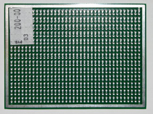
Breadboard made of textolite for quick installation
Diagram of a simple driver for a 1W LED
One of the simplest circuits for powering a high-power LED is shown in the figure below:
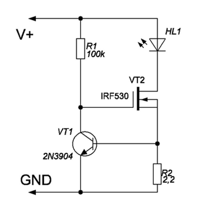
As you can see, in addition to the LED, it includes only 4 elements: 2 transistors and 2 resistors.
In the role of the regulator of the current passing through the led, here is a powerful field-effect n-channel transistor VT2. Resistor R2 determines the maximum current passing through the LED, and also works as a current sensor for transistor VT1 in the feedback circuit.
The more current passes through VT2, the more voltage drops on R2, respectively, VT1 opens and lowers the voltage at the gate of VT2, thereby reducing the LED current. Thus, stabilization of the output current is achieved.
The circuit is powered from a constant voltage source of 9-12 V, current not less than 500 mA. The input voltage must be at least 1-2 V greater than the voltage drop across the LED.
Resistor R2 should dissipate 1-2 watts of power, depending on the required current and supply voltage. Transistor VT2 - n-channel, rated for a current of at least 500 mA: IRF530, IRFZ48, IRFZ44N. VT1 - any low power bipolar npn: 2N3904, 2N5088, 2N2222, BC547, etc. R1 - with a power of 0.125 - 0.25 W with a resistance of 100 kOhm.
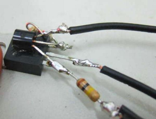
Due to the small number of elements, assembly can be carried out by surface mounting:
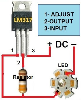
Another simple driver circuit based on the LM317 linear controlled voltage regulator:
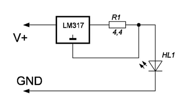
Here, the input voltage can be up to 35 V. The resistance of the resistor can be calculated using the formula:
where I is the current strength in amperes.
In this circuit, the LM317 will dissipate significant power with a large difference between the supply voltage and the LED drop. Therefore, it will have to be placed on a small one. The resistor must also be rated for at least 2 watts.
This scheme is more clearly discussed in the following video:
This shows how to connect a powerful LED using batteries with a voltage of about 8 V. With a voltage drop across the LED of about 6 V, the difference is small, and the microcircuit heats up slightly, so you can do without a heatsink.
Please note that with a large difference between the supply voltage and the drop on the LED, it is necessary to put the microcircuit on a heat sink.
Power driver circuit with PWM input
Below is a diagram for powering high-power LEDs:

The driver is based on a dual comparator LM393. The circuit itself is a buck-converter, that is, a pulsed step-down voltage converter.
Driver Features
- Supply voltage: 5 - 24 V, constant;
- Output current: up to 1A, adjustable;
- Output power: up to 18W;
- Output short circuit protection;
- The ability to control brightness using an external PWM signal (it will be interesting to read how).
Operating principle
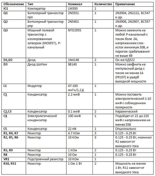
Resistor R1 with diode D1 form a reference voltage of about 0.7 V, which is additionally regulated by a variable resistor VR1. Resistors R10 and R11 serve as current sensors for the comparator. As soon as the voltage on them exceeds the reference, the comparator will close, thus closing a pair of transistors Q1 and Q2, and those, in turn, will close the transistor Q3. However, the inductor L1 at this moment tends to resume the passage of current, so the current will flow until the voltage across R10 and R11 becomes less than the reference, and the comparator again does not open transistor Q3.
The pair Q1 and Q2 acts as a buffer between the output of the comparator and the gate of Q3. This protects the circuit from false positives due to interference on the gate of Q3, and stabilizes its operation.
The second part of the comparator (IC1 2/2) is used for additional dimming with PWM. To do this, a control signal is applied to the PWM input: when TTL logic levels (+5 and 0 V) are applied, the circuit will open and close Q3. The maximum signal frequency at the PWM input is about 2 kHz. This input can also be used to turn the device on and off using the remote control.
D3 is a Schottky diode, rated up to 1 A. If you can't find the Schottky diode, you can use a switching diode, such as FR107, but the output power will then be slightly reduced.
The maximum output current is adjusted by selecting R2 and including or excluding R11. This way you can get the following values:
- 350mA (1W LED): R2=10K, R11 disabled,
- 700mA (3W): R2=10K, R11 connected, 1 ohm nominal,
- 1A (5W): R2=2.7K, R11 connected, nominal 1 ohm.
Within narrower limits, the adjustment is made by a variable resistor and a PWM signal.
Building and configuring the driver
Driver components are mounted on a breadboard. First, the LM393 chip is installed, then the smallest components: capacitors, resistors, diodes. Then transistors are put in, and in last turn variable resistor.
It is better to place elements on the board in such a way as to minimize the distance between the connected pins and use as few wires as jumpers as possible.
When connecting, it is important to observe the polarity of the diodes and the pinout of the transistors, which can be found in technical description to these components. Diodes can also be used in the resistance measurement mode: in the forward direction, the device will show a value of the order of 500-600 ohms.
To power the circuit, you can use an external DC voltage source of 5-24 V or batteries. Batteries 6F22 ("crown") and others have too little capacity, so their use is not advisable when using powerful LEDs.
After assembly, you need to adjust the output current. To do this, LEDs are soldered to the output, and the VR1 engine is set to the lowest position according to the diagram (checked with a multimeter in the “ringing” mode). Next, we apply a supply voltage to the input, and by rotating the VR1 knob we achieve the required brightness of the glow.
Item List:
Conclusion
The first two of the considered circuits are very simple to manufacture, but they do not provide protection against short circuits and have a rather low efficiency. For long-term use, the third circuit on the LM393 is recommended, as it does not have these disadvantages and has more power output adjustment capabilities.
LEDs for their power require the use of devices that will stabilize the current passing through them. In the case of indicator and other low-power LEDs, resistors can be dispensed with. Their simple calculation can be further simplified using the "LED Calculator".
To use high-power LEDs, one cannot do without the use of current-stabilizing devices - drivers. The right drivers have a very high efficiency - up to 90-95%. In addition, they provide a stable current even when the voltage of the power supply changes. And this may be relevant if the LED is powered, for example, from batteries. The simplest current limiters - resistors - cannot provide this by their nature.
You can learn a little about the theory of linear and switching current stabilizers in the article "Drivers for LEDs".
Ready driver, of course, you can buy. But it is much more interesting to do it yourself. This will require basic skills in reading electrical circuits and owning a soldering iron. Consider a few simple homemade driver circuits for high-power LEDs.
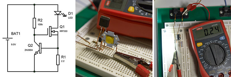
Simple driver. Assembled on a breadboard, powering the mighty Cree MT-G2
A very simple linear driver circuit for an LED. Q1 - N-channel field-effect transistor of sufficient power. Suitable, for example, IRFZ48 or IRF530. Q2 is a bipolar npn transistor. I used 2N3004, you can take any similar one. Resistor R2 is a 0.5-2W resistor that will determine the driver current strength. Resistance R2 2.2 Ohm provides a current of 200-300mA. The input voltage should not be very large - it is advisable not to exceed 12-15V. The driver is linear, so the efficiency of the driver will be determined by the ratio V LED / V IN , where V LED is the voltage drop across the LED and V IN is the input voltage. The greater the difference between the input voltage and the drop across the LED, and the greater the driver current, the more transistor Q1 and resistor R2 will heat up. However, V IN must be greater than V LED by at least 1-2V.
For tests, I built a circuit on a breadboard and powered a powerful CREE MT-G2 LED. The power supply voltage is 9V, the voltage drop across the LED is 6V. The driver worked right away. And even with such a small current (240mA), the mosfet dissipates 0.24 * 3 \u003d 0.72 W of heat, which is not at all small.
The circuit is very simple and even in the finished device can be assembled by surface mounting.
The scheme of the next homemade driver is also extremely simple. It involves the use of an LM317 step-down voltage converter chip. This microcircuit can be used as a current stabilizer.

An even simpler driver on the LM317 chip
The input voltage can be up to 37V, it must be at least 3V above the LED voltage drop. The resistance of the resistor R1 is calculated by the formula R1 = 1.2 / I, where I is the required current. The current should not exceed 1.5A. But at this current, resistor R1 should be able to dissipate 1.5 * 1.5 * 0.8 = 1.8 watts of heat. The LM317 chip will also get very hot and you cannot do without a radiator. The driver is also linear, so for maximum efficiency, the difference between V IN and V LED should be as small as possible. Since the circuit is very simple, it can also be assembled by surface mounting.
On the same breadboard, a circuit was assembled with two one-watt resistors with a resistance of 2.2 ohms. The current strength turned out to be less than the calculated one, since the contacts in the breadboard are not ideal and add resistance.
The next driver is an impulse buck. It is assembled on a QX5241 chip.
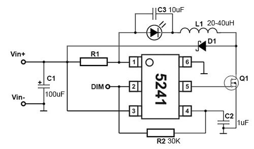
The circuit is also simple, but consists of a slightly larger number of parts, and here one cannot do without the manufacture of a printed circuit board. In addition, the QX5241 chip itself is made in a fairly small SOT23-6 package and requires attention when soldering.
The input voltage should not exceed 36V, the maximum stabilization current is 3A. The input capacitor C1 can be anything - electrolytic, ceramic or tantalum. Its capacitance is up to 100 μF, the maximum operating voltage is at least 2 times higher than the input voltage. Capacitor C2 is ceramic. Capacitor C3 - ceramic, capacitance 10uF, voltage - at least 2 times greater than the input. Resistor R1 must have a power of at least 1W. Its resistance is calculated using the formula R1 = 0.2 / I, where I is the required driver current. Resistor R2 - any resistance 20-100 kOhm. The Schottky diode D1 must withstand the reverse voltage with a margin - at least 2 times the value of the input. And it must be designed for a current not less than the required driver current. One of essential elements circuits - field effect transistor Q1. This should be an N-channel field device with the lowest possible open resistance, of course, it must withstand the input voltage and the required current strength with a margin. A good option- field-effect transistors SI4178, IRF7201, etc. Inductor L1 must have an inductance of 20-40 μH and a maximum operating current not less than the required driver current.
The number of parts of this driver is very small, they all have a compact size. As a result, you can get a fairly miniature and, at the same time, powerful driver. This is a pulse driver, its efficiency is significantly higher than that of linear drivers. However, it is recommended that the input voltage be only 2-3V higher than the voltage drop across the LEDs. The driver is also interesting in that output 2 (DIM) of the QX5241 chip can be used for dimming - controlling the driver current and, accordingly, the brightness of the LED. To do this, pulses (PWM) with a frequency of up to 20 kHz must be applied to this output. Any suitable microcontroller can handle this. As a result, you can get a driver with several modes of operation.
Ready-made products for powering high-power LEDs can be viewed.
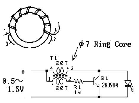
LED flashlight with 3V converter for LED 0.3-1.5V 0.3-1.5 VLEDflash light
Usually, a blue or white LED requires 3 - 3.5v to operate, this circuit allows you to power a blue or white LED with low voltage from a single AA battery.
Details:
Light-emitting diode
Ferrite ring (~10 mm diameter)
Winding wire (20 cm)
1kΩ resistor
N-P-N transistor
Battery
Parameters of the used transformer:
The winding going to the LED has ~45 turns wound with 0.25mm wire.
The winding going to the base of the transistor has ~30 turns of 0.1mm wire.
The base resistor in this case has a resistance of about 2K.
Instead of R1, it is desirable to put a tuning resistor, and achieve a current through the diode ~ 22mA, with a fresh battery, measure its resistance, then replacing it with a constant resistor of the received value.
The assembled circuit must work immediately.
There are only 2 reasons why the scheme will not work.
1. the ends of the winding are mixed up.
2. too few turns of the base winding.
Generation disappears, with the number of turns<15.
 Put the pieces of wire together and wind around the ring.
Connect the two ends of different wires together.
The circuit can be placed inside a suitable case.
The introduction of such a circuit into a flashlight operating from 3V significantly extends the duration of its operation from one set of batteries.
Variant of execution of a lamp from one battery 1,5v.

The transistor and resistance are placed inside the ferrite ring


White LED powered by a dead AAA battery
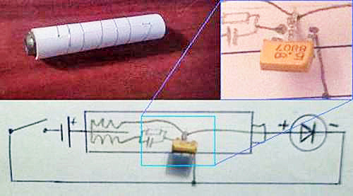
Upgrade option "flashlight - pen"
 The excitation of the blocking generator shown in the diagram is achieved by a transformer connection at T1. The voltage pulses that occur in the right (according to the scheme) winding are added to the voltage of the power source and fed to the VD1 LED. Of course, it would be possible to exclude the capacitor and resistor in the base circuit of the transistor, but then VT1 and VD1 may fail when using branded batteries with low internal resistance. The resistor sets the operating mode of the transistor, and the capacitor passes the RF component.
The circuit used a KT315 transistor (as the cheapest, but any other with a cutoff frequency of 200 MHz or more), an ultra-bright LED. For the manufacture of a transformer, a ferrite ring is required (approximate size 10x6x3 and a permeability of about 1000 HH). The wire diameter is about 0.2-0.3 mm. Two coils of 20 turns each are wound on the ring.
If there is no ring, then a cylinder similar in volume and material can be used. You just have to wind 60-100 turns for each of the coils.
Important point : you need to wind the coils in different directions.
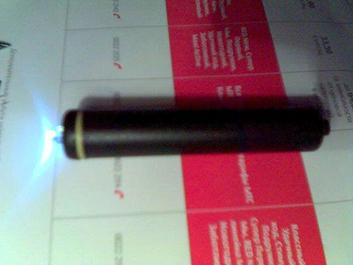
Flashlight photos:
the switch is located in the "fountain pen" button, and the gray metal cylinder conducts current.
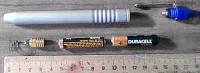
We make a cylinder according to the size of the battery.
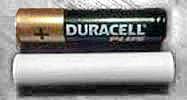
It can be made from paper, or a piece of any rigid tube can be used.
We make holes along the edges of the cylinder, wrap it with tinned wire, pass the ends of the wire into the holes. We fix both ends, but leave a piece of conductor at one of the ends: so that you can connect the converter to the spiral.
A ferrite ring would not fit into a lantern, so a cylinder of similar material was used.

Cylinder from an inductor from an old TV.
The first coil is about 60 turns.
Then the second, winds in the opposite direction again 60 or so. The threads are held together with glue.
We assemble the converter:
Everything is located inside our case: We unsolder the transistor, the resistor capacitor, solder the spiral on the cylinder, and the coil. The current in the coil windings must go in different directions! That is, if you wound all the windings in one direction, then swap the conclusions of one of them, otherwise generation will not occur.
It turned out the following:
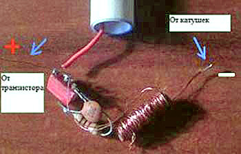
We insert everything inward, and use nuts as side plugs and contacts.
We solder the coil leads to one of the nuts, and the VT1 emitter to the other. Glue. we mark the conclusions: where we will have an output from the coils, we put “-”, where the output from the transistor with the coil we put “+” (so that everything is like in a battery).
Now you should make a "lamp diode".
Attention: on the base should be minus the LED.
Assembly:
 As is clear from the figure, the converter is a "substitute" for the second battery. But unlike it, it has three points of contact: with the plus of the battery, with the plus of the LED, and the common body (through the spiral).
Its location in the battery compartment is specific: it must be in contact with the positive of the LED.
Modern flashlightwith the mode of operation of the LED powered by constant stabilized current.
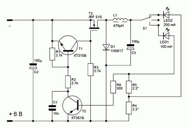
The current stabilizer circuit works as follows:
When power is applied to the circuit, transistors T1 and T2 are locked, T3 is open, because an unlocking voltage is applied to its gate through resistor R3. Due to the presence of an inductor L1 in the LED circuit, the current increases smoothly. As the current in the LED circuit increases, the voltage drop across the R5-R4 chain increases, as soon as it reaches about 0.4V, transistor T2 opens, followed by T1, which in turn closes the current switch T3. The increase in current stops, a self-induction current arises in the inductor, which begins to flow through the diode D1 through the LED and the chain of resistors R5-R4. As soon as the current decreases below a certain threshold, transistors T1 and T2 will close, T3 will open, which will lead to a new cycle of energy accumulation in the inductor. In normal mode, the oscillatory process occurs at a frequency of the order of tens of kilohertz.
About details:
Instead of the IRF510 transistor, you can use the IRF530, or any n-channel field-effect key transistor for a current of more than 3A and a voltage of more than 30 V.
Diode D1 must necessarily be with a Schottky barrier for a current of more than 1A, if you put an ordinary even high-frequency type KD212, the efficiency will drop to 75-80%.
The inductor is homemade, it is wound with a wire no thinner than 0.6 mm, better with a bundle of several thinner wires. About 20-30 turns of wire on the B16-B18 armor core are required with a non-magnetic gap of 0.1-0.2 mm or close to 2000NM ferrite. If possible, the thickness of the non-magnetic gap is selected experimentally according to the maximum efficiency of the device. Good results can be obtained with ferrites from imported inductors installed in switching power supplies, as well as in energy-saving lamps. Such cores have the form of a thread spool, do not require a frame and a non-magnetic gap. Coils on toroidal cores made of pressed iron powder, which can be found in computer power supplies (they are wound with output filter inductors), work very well. The non-magnetic gap in such cores is evenly distributed in volume due to the production technology.
The same stabilizer circuit can also be used in conjunction with other batteries and batteries of galvanic cells with a voltage of 9 or 12 volts without any change in the circuit or cell ratings. The higher the supply voltage, the less current the flashlight will consume from the source, its efficiency will remain unchanged. The stabilization current is set by resistors R4 and R5.
If necessary, the current can be increased up to 1A without the use of heat sinks on the parts, only by selecting the resistance of the setting resistors.
The charger for the battery can be left "native" or assembled according to any of the known schemes, or even use an external one to reduce the weight of the flashlight.
LED flashlight from calculator B3-30
The converter is based on the B3-30 calculator circuit, in the switching power supply of which a transformer with a thickness of only 5 mm is used, which has two windings. Using a pulse transformer from an old calculator made it possible to create an economical LED flashlight.
The result is a very simple circuit.
 The voltage converter is made according to the scheme of a single-cycle generator with inductive feedback on a transistor VT1 and a transformer T1. The impulse voltage from the windings 1-2 (according to the B3-30 calculator circuit diagram) is rectified by the VD1 diode and fed to the super-bright HL1 LED. Capacitor C3 filter. The design is based on a Chinese-made flashlight designed to install two AA batteries. The transducer is mounted on a printed circuit board made of one-sided foil-coated fiberglass with a thickness of 1.5 mmfig.2sizes that replace one battery and inserted into the flashlight instead of it. A contact made of double-sided foil fiberglass with a diameter of 15 mm is soldered to the end of the board marked with a “+” sign, both sides are connected by a jumper and soldered.
After installing all the parts on the board, the “+” end contact and the T1 transformer are filled with hot glue to increase strength. The layout of the lantern is shown infig.3and in a particular case depends on the type of lamp used. In my case, no modification of the lamp was required, the reflector has a contact ring, to which the negative output of the printed circuit board is soldered, and the board itself is attached to the reflector with hot glue. The printed circuit board assembly with the reflector is inserted instead of one battery and clamped with a cover.
 The voltage converter uses small parts. Resistors of the MLT-0.125 type, capacitors C1 and C3 are imported, up to 5 mm high. Diode VD1 type 1N5817 with a Schottky barrier, in its absence, you can use any rectifier diode that is suitable for the parameters, preferably germanium due to the lower voltage drop across it. A properly assembled converter does not need to be adjusted if the transformer windings are not reversed, otherwise swap them. In the absence of the above transformer, you can make it yourself. Winding is carried out on a ferrite ring of size K10 * 6 * 3 with a magnetic permeability of 1000-2000. Both windings are wound with PEV2 wire with a diameter of 0.31 to 0.44 mm. The primary winding has 6 turns, the secondary 10 turns. After installing such a transformer on the board and checking its performance, it should be fixed on it with hot glue.
Flashlight tests with an AA battery are presented in Table 1.
The test used the cheapest AA battery costing only 3 rubles. The initial voltage under load was 1.28 V. At the output of the converter, the voltage measured on a superbright LED was 2.83 V. The brand of the LED is unknown, the diameter is 10 mm. The total current consumption is 14 mA. The total operating time of the flashlight was 20 hours of continuous operation.
When the voltage on the battery drops below 1V, the brightness drops noticeably.
| Time, h | V batteries, V | V conversion, V |
| 0 | 1,28 | 2,83 |
| 2 | 1,22 | 2,83 |
| 4 | 1,21 | 2,83 |
| 6 | 1,20 | 2,83 |
| 8 | 1,18 | 2,83 |
| 10 | 1,18 | 2.83 |
| 12 | 1,16 | 2.82 |
| 14 | 1,12 | 2.81 |
| 16 | 1,11 | 2.81 |
| 18 | 1,11 | 2.81 |
| 20 | 1,10 | 2.80 |
Homemade flashlight with LEDs
The basis is a flashlight "VARTA" powered by two AA batteries:
Since diodes have a highly non-linear IV characteristic, it is necessary to equip the flashlight with a circuit for operating on LEDs, which will provide a constant brightness of the glow as the battery is discharged and will remain operational at the lowest possible supply voltage.
The heart of the voltage regulator is the MAX756 micropower DC/DC boost converter.
According to the declared characteristics, it works when the input voltage drops to 0.7V.
Switching scheme - typical:

 Mounting is carried out in a hinged way.
Electrolytic capacitors - tantalum CHIP. They have a low series resistance, which improves efficiency somewhat. Schottky diode - SM5818. Chokes had to be connected in parallel, because. there was no suitable value. Capacitor C2 - K10-17b. LEDs - superbright white L-53PWC "Kingbright".
As you can see in the figure, the whole circuit easily fit into the empty space of the light emitting node.
The output voltage of the stabilizer in this switching circuit is 3.3V. Since the voltage drop across the diodes in the nominal current range (15-30mA) is about 3.1V, the extra 200mV had to be extinguished by a resistor connected in series with the output.
In addition, a small series resistor improves load linearity and circuit stability. This is due to the fact that the diode has a negative TCR, and when it is heated, its direct voltage drop decreases, which leads to a sharp increase in current through the diode, when it is powered from a voltage source. It was not necessary to equalize the currents through the diodes connected in parallel - no difference in brightness was observed by eye. Moreover, the diodes were of the same type and taken from the same box.
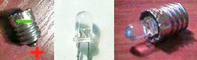
Now about the design of the light emitter. As you can see in the photos, the LEDs in the circuit are not soldered tightly, but are a removable part of the structure.
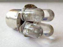
 The native light bulb is gutted, and 4 cuts are made in the flange from 4 sides (one was already there). 4 LEDs are arranged symmetrically in a circle. The positive leads (according to the diagram) are soldered to the base near the cuts, and the negative leads are inserted from the inside into the central hole of the base, cut off and also soldered. "Lamp diode", inserted in place of a conventional incandescent light bulb.
Testing:
The stabilization of the output voltage (3.3V) continued until the supply voltage dropped to ~1.2V. The load current in this case was about 100mA (~ 25mA per diode). Then the output voltage began to gradually decrease. The circuit has switched to a different mode of operation, in which it no longer stabilizes, but outputs everything it can. In this mode, it worked up to a supply voltage of 0.5V! The output voltage at the same time dropped to 2.7V, and the current from 100mA to 8mA.
A little about efficiency.
 The efficiency of the circuit is about 63% with fresh batteries. The fact is that the miniature chokes used in the circuit have an extremely high ohmic resistance - about 1.5 ohm
The solution is a µ-permalloy ring with a permeability of about 50.
40 turns of PEV-0.25 wire, in one layer - it turned out about 80 μG. The active resistance is about 0.2 Ohm, and the saturation current, according to calculations, is more than 3A. We change the output and input electrolyte to 100 microfarads, although without prejudice to efficiency it can be reduced to 47 microfarads.
The advantages of LED paws have been discussed repeatedly. The abundance of positive feedback from users of LED lighting willy-nilly makes you think about Ilyich's own light bulbs. Everything would be nice, but when it comes to costing the conversion of an apartment to LED lighting, the numbers are a little “strain”.
To replace an ordinary 75W lamp, there is a 15W LED bulb, and a dozen of such lamps need to be changed. With an average cost of about $ 10 per lamp, the budget is decent, and the risk of acquiring a Chinese “clone” with a life cycle of 2-3 years cannot be ruled out. In light of this, many are considering the possibility of self-manufacturing these devices.
The most budget option can be assembled with your own hands from these LEDs. A dozen of these little ones cost less than a dollar, and are as bright as a 75W incandescent bulb. Putting everything together is not a problem, but you can’t connect them directly to the network - they will burn out. The heart of any LED lamp is the power driver. It depends on how long and well the light bulb will shine.
To assemble a 220 volt LED lamp with our own hands, let's look at the power driver circuit.
Network parameters significantly exceed the needs of the LED. In order for the LED to be able to work from the network, it is required to reduce the voltage amplitude, current strength and convert the AC voltage to DC.
For these purposes, a voltage divider with a resistor or capacitive load and stabilizers are used.
LED Light Components
A 220 volt LED lamp circuit will require a minimum number of available components.
- LEDs 3.3V 1W - 12 pcs.;
- ceramic capacitor 0.27uF 400-500V - 1 pc.;
- resistor 500kΩ - 1MΩ 0.5 - 1W - 1 sh.t;
- 100V diode - 4 pcs.;
- electrolytic capacitors for 330uF and 100uF 16V, 1 pc.;
- voltage regulator for 12V L7812 or similar - 1 pc.
Making a 220V LED driver with your own hands
The 220 volt ice driver circuit is nothing more than a switching power supply.
As a homemade LED driver from a 220V network, consider the simplest switching power supply without galvanic isolation. The main advantage of such schemes is simplicity and reliability. But be careful when assembling, since such a circuit does not have a limit on the output current. The LEDs will take their prescribed one and a half amps, but if you touch the bare wires with your hand, the current will reach ten amperes, and such a current shock is very noticeable.
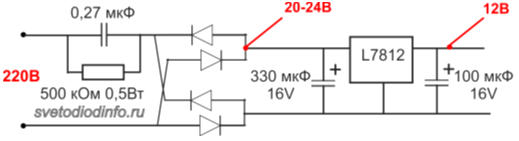
The simplest driver circuit for 220V LEDs consists of three main stages:
- Voltage divider on capacitance;
- diode bridge;
- voltage stabilization stage.
First cascade- capacitance on the capacitor C1 with a resistor. The resistor is necessary for the self-discharge of the capacitor and does not affect the operation of the circuit itself. Its value is not particularly critical and can be from 100kΩ to 1MΩ with a power of 0.5-1W. The capacitor is necessarily not electrolytic for 400-500V (effective peak voltage of the network).
When a half-wave of voltage passes through a capacitor, it passes current until the plates are charged. The smaller its capacity, the faster the full charge. With a capacity of 0.3-0.4 μF, the charging time is 1/10 of the half-wave period of the mains voltage. In simple terms, only a tenth of the incoming voltage will pass through the capacitor.
Second cascade- diode bridge. It converts AC voltage to DC. After cutting off most of the voltage half-wave by the capacitor, we get about 20-24V DC at the output of the diode bridge.
Third cascade– smoothing stabilizing filter.
A capacitor with a diode bridge acts as a voltage divider. When the voltage in the network changes, the amplitude at the output of the diode bridge will also change.
To smooth out the voltage ripple, we connect an electrolytic capacitor in parallel with the circuit. Its capacity depends on the power of our load.
In the driver circuit, the supply voltage for the LEDs must not exceed 12V. As a stabilizer, you can use the common element L7812.
The assembled circuit of the 220 volt LED lamp starts working immediately, but before connecting to the network, carefully insulate all bare wires and solder points of the circuit elements.
Driver option without current stabilizer
There are a huge number of driver circuits for LEDs from a 220V network on the network that do not have current stabilizers.

The problem of any transformerless driver is the ripple of the output voltage, and therefore the brightness of the LEDs. A capacitor installed after the diode bridge partially copes with this problem, but does not completely solve it.
There will be a ripple with an amplitude of 2-3V on the diodes. When we install a 12V regulator in the circuit, even taking into account the ripple, the amplitude of the incoming voltage will be above the cutoff range.
Voltage diagram in a circuit without a stabilizer

Diagram in a circuit with a stabilizer

Therefore, a driver for diode lamps, even assembled by oneself, will not be inferior in terms of pulsation to similar units of expensive factory-made lamps.
As you can see, assembling a driver with your own hands is not particularly difficult. By changing the parameters of the circuit elements, we can vary the values of the output signal over a wide range.
If you have a desire to assemble a 220 volt LED spotlight circuit based on such a circuit, it is better to convert the output stage to 24V with an appropriate stabilizer, since the output current of the L7812 is 1.2A, this limits the load power to 10W. For more powerful lighting sources, you either need to increase the number of output stages, or use a more powerful stabilizer with an output current of up to 5A and install it on a radiator.